While Bochs is a good tool when the speed is not a limiting factor, there are times where we need to see the printer events at full speed. This is somewhat more complex and we will need to compile a special kernel to host our capturing tool.
There is a kernel extension known as RT-Linux valuable for this kind of signal processing, allowing us to use a second computer as a logic analyzer of low cost. RT-Linux let we have full control of our machine, running the regular Linux kernel as a lower priority task or thread than its specially designed threads. Suppose that this second machine, or spy machine, will be connected to a modified "T" printer cable and can capture all signal modification occured during some time interval. We can also set some triggering condition for starting the capture or filter what is important to be stored. It can be seen that this logic analyzer is even better than many commercial instruments available. And if we run the printer from a slower computer than our spy, we can get every detail on the parallel port signals.
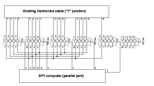
You will need to open the DB-25 connector of a standard PC-to-printer cable and solder several wires, with care for not disturbing the present connections. Then at the other side of these wires, you put another DB-25 connector, that will be attached to a printed circuit or perforated or even other solderless board with some TTL data buffers as a kind of data selector. This is needed because our parallel port only have 5 input signals (we could save one part, but we choose to stay with just 4 signals for simplicity) and we will select which signals to spy by lowering the level of only one such buffers at a time. In the circuit given, for example, the SEL_HIGH_DATA selection corresponds to the value 11111110 (binary) being output through the spy's data port. BASEPORT is the base address of the spy's parallel port, usually 0x378 (but could be 0x3bc, check your /proc/ioport for your parport0 device).
Fortunately, only a small number of signals are present at the port: 8 data signals, 4 control signals and 5 status signals. With a simple circuit like this: (you may also get the xfig original circuit)
and a small real time thread code like this:
void *lpt_thread_code( void *data ){
    int rb1,rb2;
    int cnt=4095;
    while (cnt--) {
        while (!(inb(BASEPORT+1)&STB))
            ;
        outb(SEL_HIGH_DATA,BASEPORT);
        rb1 = (inb(BASEPORT+1) << 1)&0xf0;
        outb(SEL_LOW_DATA,BASEPORT);
        rb2 = ((inb(BASEPORT+1) >> 3)&0x0f) | rb1;
        rtf_put(1,&rb2,1);
        while ((inb(BASEPORT+1)&STB))
            ;
    }
    pthread_wait_np();
    return NULL;
}
it will be possible, for instance, get strobed data until our buffer is full and then collect the gathered data from a /dev/rtf0 fifo device fed by our real time module. The drawback is, when the thread code is active, no other activity can take place in our spy machine, not even time interrupts, nor keyboard events, nothing, nada, niente. That's why it is crucial to have a well designed thread or we will have to push the reset button too much and wait for fsck!
The code given is very easily understood. First it will wait until the STB signal is low (because it is inverted), at the first while loop. Then, it will get the four most significant bits from the data bus of the spied port, on its control port, shift them to align with bit position d7-d4 and finally repeat the procedure with the least significant position, shifting to the right and combining with the first 4 bits. The call to rtf_put will make the result available later when the acquisition phase finish. The last while statement will wait for the release of the STB signal. Of course, this code doesn't work with a GDI printer, because it doesn't honor the STB or other standard lpt signals, but this illustrate what kind of procedures we want to code. The counter cnt limit our acquisition so we don't stay hang forever. And the pthread_wait_np() call make the thread stop till the next period (that will never arrive).
The real time fifo can be read as any other character device, for instance, just cat'ing the /dev/rtf0 device or copying it to a file. This thread code is not magic. You must make many experiment changing the code to suit to your printer protocol. A good first try is to get all ports, save it in a temporary integer and comparing each time with the value read before. When the value differ, you put it in the fifo and save it in the temporary variable and repeat the process. Then look at the captured data to see any interesting pattern on it.
It is out of scope to explain here how to compile and install RT-Linux. But when you make RT device drivers remember you are in a lower level position then even the kernel, and as such, no printk or other non-reentrant kernel functions can possibly be called. There are a few library routines available from RT-Linux site, but we don't really need many. You can make your real time thread communicate by shared memory, but fifos are easier to work for streamed data like we have. You can have a time stamp attached to your readings, by calling clock_gethrtime( rtl_getschedclock() ). It returns the current real time scheduler time in nanoseconds units. Some parallel port pins have inverted logic. Please don't invert them at the real time. You need most of the CPU time for gaining speed. Instead, save them scrambled and make a utility routine to post-process your data.
We can implement many triggering sources, both by analysing the signals, as well as letting the start of the real time thread after some event. For instance, if the interesting part of your measurement can be defined by your hearing of the printer sound, you can have a manual trigger. To implement it, create a command fifo (say /dev/rtf1), put the following: rtf_create_handler(IN_FIFO, &cmd_handler); at the init_module function, and make an external (user level) procedure pipe the command into the IN_FIFO device (defined by #define IN_FIFO 1). Generally you will need a most sophisticated triggering procedure. Use counters in the thread code for starting to capture after "n" times a given event occurs, so you will have a window into the data gathered.
I am lucky because my printer didn't required so much real time tools to be analyzed. Next time I will show some reasoning I used to understand the compressed data and what kind of patterned data I did send to the printer, drawn by Xpaint and printed by MS-Paintbrush at the Bochs virtual machine side.